Hints and Tips
Content
General
- Who needs to test steam quality?
- What is the difference between EN 285 and HTM 2010?
- Testing frequency
- Test Procedures
- Regulatory Approach
- Validation of the SQ1 Portable Steam Quality Test Kit
- Accuracy – Dryness Value & Superheat
- Accuracy – Non-condensable gas test
Non-Condensable Gas Test
- Background
- De-aerators
- The Non-Condensable Gas Test
- Pressure/Temperature Comparison
Dryness Value Test
- Background
- Calorimetry
- Acceptance Criteria
- Methodology Problems
- Causes of Wet Steam – Plant Steam
- Causes of Wet Steam – Pure/Clean Steam
Superheat Test
- Background
- Acceptance Criteria
- Methodology Problems
General
Who needs to test steam quality?
Manufacturers and processors of sterile products and medical devices within Europe and those who supply Europe. The requirement is restricted to the porous loads/dry goods/equipment processes, which impact on the sterility of finished products.What is the difference between EN 285 and HTM 2010? HTM 2010 is a UK National Health Service guidance document. It was produced
in anticipation of EN 285 and seeks to provide guidance to hospitals to allow their compliance with EN 285. EN 285 is a European standard for Sterilization – Steam Sterilizers– Large Sterilizers, which describes the steam quality tests and is the definitive reference.
Testing frequency
The only references to the frequency of steam, quality testing are to be found in HTM 2010, where it is indicated that steam quality should be tested as part of the annual revalidation exercise for each sterilizer. Where steam systems are either routinely or irregularly shut down, large quantities of air will be present in the distribution system on restarting. It is recommended that in such circumstances a comprehensive and validated venting procedure should be applied and testing for non-condensable gases may be appropriate.
Test Procedures
The standard test procedures require the steam quality to be sampled when steam is first admitted to the sterilizer chamber after a cycle is started. While this provides a reference condition, it may be inadequate to fully characterise the steam system which may perform differently under different flow conditions. It is suggested that the steam supplies should be tested under both low and full flow conditions and particularly for the non-condensable gas test, include conditions where the feed water pump switches on and off (where applicable). Where aerated water is present, the worst case condition is invariably when water enters the steam generator.
Regulatory Approach
As far as we understand, our equipment has not been the subject of specific European regulatory scrutiny, though the results generated by it has, without comment on the equipment or indeed methodology. The approach of the regulators would seem to be:
Are the consequences of poor steam quality understood?
Have tests been conducted, and what are the results?
If out of specification, what action is being taken?
Validation of the SQ1 Portable Steam Quality Test Kit
The SQ1 Portable Steam Quality Test Kit is supplied with a Certificate of Conformity that details that the equipment supplied dimensionally complies with the requirements of EN 285. It will be seen that the test methods are relatively simple and cannot be referenced to standards. The equipment may be used as supplied with confidence and no validation of the SQ1 Portable Steam Quality Test Kit is required. While the non-condensable gas test equipment is fitted with a contact thermometer, this is for indication only and does not require calibration. Associated data logging and weighing equipment must be be calibrated. See statements on accuracy, below.
Accuracy – Dryness Value & Superheat
The equipment supplied complies exactly with EN 285. These tests are approximations and inferential respectively. The tests are conducted in accordance with EN 285 or HTM 2010 and the results used accordingly. It is therefore not possible to benchmark these tests with any standard.
Accuracy – Non-condensable gas test
For non-condensable gas testing we state that our equipment complies with EN 285 as this standard specifically allows the use of alternative methods provided they have been shown to give comparable results. This comparison work has been undertaken and the results showed that the difference between the EN 285 method and our system for non-condensable gas tests was 0.03% over five tests with values between 0.4 and 1.6%.
Non-Condensable Gas Test
Background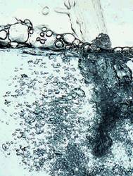 These gases will usually be air, though carbon dioxide may be present in relatively large quantities as the consequence of certain water treatment processes, typically water softeners. This is exacerbatedby excessive aeration that can exist in many pharmaceutical water treatment plants where water is constantly recirculated and sprayed into the top of storage vessels. The effect of such gases being present in the steam supply to a sterilizer can be the same as inadequate air removal, that is to say
instead of components being heated by steam condensing on them, they are heated by a mixture of steam and other gases. When steam condenses its volume reduces dramatically causing more steam to flow into the void left. If gases are present in the steam, it will be seen that the flow of steam forces the gases towards load components where they can accumulate.
The presence of these gases causes two problems:
- Air is an insulator having resistance to heat transfer some 12,000 times greater than copper. Either a layer or pocket of air can result in the heating process being adversely affected.
- Either a layer or pocket of air may cause a physical barrier to steam/moisture reaching all parts of the load. The presence of moisture being essential to the sterilization process by allowing the walls of cells to coagulate.
 The Bowie Dick Test result shown below is a result of a sterilizer where some 6.5% of non-condensable gases were present in the steam supply. In order for a uniform colour change to occur, the correct temperature must be present for the correct time and moisture must be present. The failure of the centre portion to change colour clearly shows the presence of air or other gases. The clear circle in the centre graphically illustrates how residual air or non-condensable gases are forced to the centre of load components by steam flowing towards the load.
While non-condensable gases are almost always the result of supplying steam generators with cold feed water, poorly designed steam distribution systems may allow the relatively small volumes of gases that are inevitably produced with the steam to accumulate in the distribution system which may be displaced in high concentration packets. This may be resolved by the installation of well placed steam traps and air vents.
Generally, if poor quality steam is generated, it will not be improved by the distribution system. While air vents and steam traps may eliminate non-condensable gases under low or no flow conditions, under high flow conditions such gases will invariably be entrained within the steam and will be carried with it to the point of use. Typically, steam flows at 25 – 35 m/s (56 – 78 mph) and it is hard to conceive it separating under such conditions. It is for this reason that testing at the point of use is deemed necessary.
Most steam generators have integral feed water heaters as part of their design. In most cases, these are present to recover heat from plant steam condensate and blow down heat exchanges. In these cases, unless any gases are allowed to leave the feed water system, they will be carried by the flow of water into the steam generator. Simple heating processes such as these will have no impact on the level of on-condensable gases in the steam. The water must be heated externally to the steam generator and gases allowed to leave. This indicates an external tank.
De-aerators
Commercial de-aerators atomise water to present a large surface area and the resulting aerosol is heated with a contra flow of low pressure steam. The steam heats the water close to the saturation temperature (boiling point for the pressure present) and physically strips away the resulting air bubbles on the water surface. Often a vacuum pump will be fitted to draw off the resulting steam/gas mixture.
Other causes of non-condensable gases are:
- Leaking glands on steam generator feed water pumps allowing air to be pumped into the steam generator each time the feed water pump operates.
- Leaking glands on steam valves where a venturi effect can cause air to be drawn into steam distribution systems.
- Where steam systems are either routinely or irregularly shut down, large uantities of air will be present in the distribution system on restarting. It is recommended that in such circumstances a comprehensive venting procedure should be applied and testing for non-condensable gases may be appropriate.
The Non-Condensable Gas Test
 The method of conducting the non-condensable gas test described in HTM 2010/EN 285 requires considerable skill to obtain repeatable test results. The water used for the tests should be degassed by boiling and allowing to cool in a closed container. If this is not done, gases will be released from the water in addition to that coming from the steam supply.
This may result in high values being encountered. This is exacerbated by the speed at which the test is carried out, the rate determining whether high or low results are obtained. Generally, the faster the test is conducted, the higher the test result. In many respects the test method is subjective. The test has to be completed when the cooling water temperature reaches 70 degrees celsius. It will be seen that to properly test the steam, it may be necessary to test under different flow conditions. The time involved in draining and replacing the cooling water may cause vital information to be lost and an incomplete picture formed.
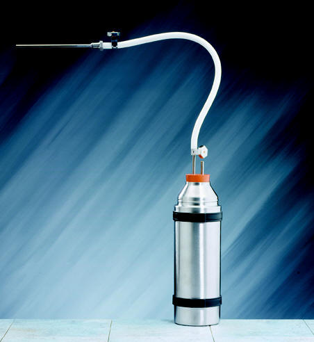
These problems are avoided when using the SQ1 Portable Steam Quality Test Kit, which utilises a condenser. This prevents the steam
coming into contact with the cooling water and avoids problems due to its aeration. The only source of gases can be from the steam. Also, the tests can be carried out for an indefinite time, allowing the steam supply to be tested under a range of flow conditions, in addition to the reference conditions described in the test methodology.
Using the SQ1 Portable Steam Quality Test Kit, the test simply condenses a sample of steam taken from the top of the steam supply pipework and collects any resulting gases in a burette. The test result is expressed as ml of gas/ml of condensate which is described as a percentage. The amount of gas collected per 100ml of condensate should not exceed 3.5 ml, described as > 3.5%. The same limit is applied by both HTM 2010 and EN 285. It should be noted that 100ml of water will generate 169.4 litres of steam at atmospheric pressure and while the result is expressed as a percentage, by volume of gas:steam the actual value is 0.00206%, a very small value.
Pressure/Temperature Comparison
It is often believed that a simple pressure/temperature comparison using steam tables will allow the presence of non-condensable gases to be discovered. If 1% of air by volume were to be present in the steam supply, a value many times in excess of the 3.5 % limit (0.00206% by volume), using Daltons Law, it will be seen from the table below that the resulting temperature depression will only be 0.33 degrees celsius. Given the differences in response times and calibration errors between pressure and temperature instruments, it will be seen that such a comparison will only detect very large and wholly unacceptable levels of gases (between 1 and 10%).
| Total Pressure in Chamber ( Bar ) |
Chamber Content (litres) Steam : Air |
Dalton’s Law Steam + Air Pressure (Bar) + Pressure (Bar) |
Chamber Temperature (°C) |
| 2. 10 | 1000 : 0 | 2.10 + 0 | 121. 8 |
| 2.10 | 900 : 100 | 1.89 + .21 | 118.5 |
| 2.10 | 990 : 10 | 2.079 + .021 | 121.47 |
| 2.10 | 999 : 1 | 2.0979 + .0021 | 121.77 |
 The theory of steam flowing through a pipe indicates that any gases present will be adjacent to the pipe wall. Within this will be a layer of condensate and further condensate will be present on the bottom of the pipe.
It will be seen that if the sample point is larger than specified a greater proportion of gas will be collected and tend to give a higher result. For
this reason the dimensions of the sample point should be as specified. Similarly, if the sample is fitted at the bottom of the pipe the
result is likely to be lower because of the larger volume of condensate present.
Dryness Value Test
Background Wet steam is undesirable as it has less energy than dry steam and more importantly can cause wet loads. The packaging used for sterile products prevents reinfection when dry, but its bacterial retentive properties will be adversely affected by the presence of moisture. Wet loads can be considered to be unsterile. The amount of moisture present in steam is measured by the dryness fraction, which is directly proportional to the amount of latent heat present. The dryness fraction describes how dry steam is with a value of 1 representing steam that is 100 dry and therefore free of entrained moisture. Steam with a dryness fraction of 0.99 consists of 99% steam and 1% water. Similarly, steam with a dryness fraction of 0.95 consists of 95% steam and 5% water. If we measure the latent heat present in steam that has a dryness fraction of 0.99 we will find that it possesses 99% of the full quotient of latent heat. By establishing the amount of latent heat present in steam we can determine its dryness fraction.
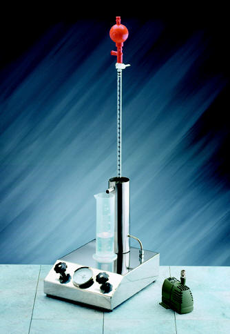
Calorimetry
We measure the latent heat in steam by condensing a sample in a known volume of water having a known starting temperature. The increase in mass of the water represents the amount of steam utilised to heat the water to its new, higher temperature. From this simple exercise we can calculate the amount of energy in the steam. If we also measure the temperature of the steam supply we can determine from steam tables the latent heat that would be present if the steam was 100% dry. By comparing the two values we establish the dryness fraction of the steam sample. Because the steam is sampled only from the centre of the pipe and does not take into account moisture on the pipe wall or condensate at the bottom of the pipe, the test is deemed to be an approximation rather than an absolute value. For this reason, instead of using the term dryness fraction, the test method uses the term Dryness Value, and this term is always used when describing test results for steam for sterilization. The calculation provided by HTM 2010 takes account of the heat loss from the test kit by the use of a constant that is dependent on the test equipment used. When using the SQ1 Portable Steam Quality Test Kit this constant has been modified to take account of the stainless steel vacuum flask and dip tube construction. This variation is detailed in the calculation in the manual and in the Excel calculation provided on floppy disk. EN285 does not specify the construction of the test equipment that should be used or provide any information on how the constant is calculated.
Acceptance Criteria
The dryness value of the steam should be equal to or greater than 0.9 for porous loads or 0.95 where metal loads are processed. Invariably this means the latter limit is applicable. In any event, in plant steam terms, steam containing 5% of moisture would be seen to be of poor quality and a dryness value of 0.99 would be more commonly seen to be acceptable.
Methodolgy Problems
Out of specification results are often caused by the test method not being strictly followed. Where the test point is not as indicated problems can easily result. Similarly, modifications to the test points by the installation of valves and/or additional pipe fittings etc. can result in additional heat losses being encountered which are not taken into account by the calculation.
The start and end temperatures within the flask should be established by agitating the flask and water until a constant value is reached. The test should be completed when the water temperature reaches 80o C. If the temperature is hotter or localised boiling occurs, energy will be lost in the form of steam venting from the flask and misleading results obtained. To avoid this the flask should be constantly, but gently agitated during the course of the test, and preferably the test completed before rather than after the 80o C limit is reached. It will be found that the effects of agitation following the test will tend to result in an increased temperature rather than a lowering. The use of a sheathed temperature sensing probe results in a relatively slow response time for small changes in temperature and time must be allowed for the sensor to stabilise.
If the test is carried out too slowly, the heat losses tend to increase and have a greater impact as time progresses. The purpose of the pitot tube is simply to provide a controlled flow of steam into the vacuum flak. It is our experience that the use of a pitot tube one size larger than that specified by the standard test method will provide a suitably fast test to avoid such problems. Provided that the water in the flask is not allowed to boil and heat to be lost from the system as steam/vapour, the size of the pitot tube is immaterial. When we conduct the test, we aim to complete it within 10 minutes.
Great care should be taken with mass measurements and weighing equipment must discriminate to 0.1g. Water droplets on surfaces of the flask that is not subject to the heating effects of the steam can affect the results if present in sufficient quantities. In between tests it is recommended that the flask is dried internally and externally and that fresh water is added in such a fashion that it is not splashed on the outer surface of the flask. When agitating the flask, care should be taken to prevent any loss of water which will affect the outcome of the test.
The temperature of the steam supply should be logged in order that its average temperature may be calculated for the duration of the test. While the pressure of the steam supply would not be expected to fluctuate by more than 10% (EN 285) any fluctuations not recorded will cause misleading results to be generated.
Causes of Wet Steam – Plant Steam
Wet steam may be caused by excessive pressure drops on the boiler due to high demands. As the pressure drops, the size of steam bubbles increase in turn increasing the volume of water in the boiler and causing it to be closer to the steam outlet. The increased size of the steam bubbles results in a more aggressive boiling action, which causes more/larger droplets of water to leave the water surface and enter the steam space and thus be carried over into the steam.
Steam at a low pressure occupies more space than steam at a high pressure and a further affect of a pressure reduction is to increase the velocity of the steam leaving the boiler. This can reach such a velocity that it will take some of the boiler water with the steam.
Certain contaminants in the boiler water can cause a froth to form on the water surface, again allowing moisture to enter the steam supply.
Once in the distribution system, the quality of steam is likely to deteriorate as the result of heat losses causing further condensation. To minimise such deterioration, the steam distribution system should be well insulated and be provided with a well designed and installed condensate removal system (steam traps and separators). Pipework should always have a fall towards steam traps. A common problem that causes wet steam is where pipework is sagging. This allows pockets of water to accumulate until they are sufficiently large to occlude the steam pipe, causing the increased steam velocity to carry them to the points of use in discrete slugs.
Causes of Wet Steam – Pure/Clean Steam
Pyrogen free steam produced by a clean/pure steam generator should be dry saturated (dryness value of 1). That is to say it should be dry and at its saturation temperature (boiling point for its given pressure). Pure steam generators are normally fitted with a pressure sustain valve which prevents excessive pressure drops and therefore the potential to carry over water with the steam. This valve will prevent pressure drops at the generator by maintaining the generators internal pressure at the expense of the distribution system. As with plant steam its quality can only deteriorate within the steam distribution system as described above, where the same design requirements apply to insulation and condensate removal.
Superheat Test
Background Superheated steam is steam at a temperature above its boiling point for its pressure. Superheated steam is a clear colourless gas that will not condense until its temperature drops to its
boiling point. Until this occurs the moisture necessary for sterilization cannot be produced and therefore presents a risk to the process. Superheated steam acts as hot air and requires sustained high temperatures and long hold times before sterilization can occur.
While superheated steam is not usually intentionally generated in the healthcare or pharmaceutical industries it can be produced as the result of excessive pressure drops. If we reduce steam from a high to a low pressure its energy level will remain the same. This high energy level will initially result in any moisture present in the steam to be evaporated. Any additional energy will then result in a temperature increase in the steam and the superheat phenomena will become evident.
Because the superheat will reduce as heat is transferred to the load, this is generally a temporary phenomena at the start of the sterilizing period. Superheated steam has the greatest adverse impact where high temperature/short time sterilizing cycles are used, typically 134C for 3 minutes as commonly used in healthcare applications. In this case, should the duration of the superheat last the full 3 minutes, sterilization would not occur. Should the same phenomena be present for 3 minutes of a 30 minute sterilization period, the impact is restricted to the initial 10% of the holding period. Despite, the impact being duration dependent, good practice indicates that superheated steam should not be tolerated.
EN 285 indicates that pressure drops should not exceed a ratio of 2:1. If the pressure drops occur sufficiently far away from the sterilizer it will be found that any superheat generated will diminish as it loses energy to the pipe walls and any moisture present.
Acceptance Criteria
When steam is reduced from line pressure to atmospheric using the pitot and expansion tube shown, the temperature measured should not exceed 25C above boiling temperature for the atmospheric pressure at the test point (typically the measured value should not exceed 125°C). It is stressed that the limit describes the maximum temperature and that no minimum value applies to this test. The assumption made by the standards, but not specified, is that if this limit is not reached, when the steam expands into the chamber its condition will be satisfactory. In this respect, the test is predictive and its worth is dependent upon the specific configuration of the sterilizer with respect to the pressure drops involved after the test point and any further conditioning that may occur from steam separators etc.
Methodology Problems
The temperature sensor should be sufficiently small to not represent a large heat sink which will dissipate any superheat. A bare thermocouple is best in this respect. The thermocouple should be moved across the steam jet issuing from the pitot tube until the highest temperature is reached. The value achieved will depend on the dryness of the steam and the size of the pressure drop involved.